An operational amplifier (op-amp) is a multi-stage, dc coupled amplifier with a very high gain and temperature stability. The voltage-controlled, voltage amplifying circuit usually consists of a large number of transistors and resistors contained in a single chip.
A typical device has a differential input, a single-ended output, and a very high gain. Because of its high gain, the output is usually several thousand times the difference between the input signals. However, in most practical applications, the operational amplifiers work with external components that provide feedback and dictate the functionality. kaizentechnology.co.uk provides electronic manufacturing services that will turn your ideas like this into reality.
The ability to customize the operational amplifiers makes them great building blocks for a variety of analog and digital applications. In addition, op-amps have several characteristics that make them ideal for a diverse range of applications. This includes the stability over a wide range of temperature and frequency ranges, very high input impedance, a zero output resistance, and more.
Typical application areas include performing
- Mathematical functions such as summation, subtraction, differentiation, and integration.
- Signal conditioning applications such as voltage regulation, analog-to-digital or digital-to-analog conversion, active filters, etc.
- Instrumentation functions such as level detection
Usually contained in a single chip, the linear device consists of several closely matched transistors and other discrete components housed in the same environment.
Although it is possible to make the operational amplifier using discrete components the resulting circuit will require larger physical space. Also, it is difficult to optimize many external components and circuits compared to integrating everything into a chip. Getting closely matched discrete components can be a challenge, and this will cause some imbalances and inefficiencies.
Basic features of an op-amp
The op-amp comprises two input terminals with opposite polarity (inverting and non-inverting), two power supply terminals (positive and negative), and an output terminal. The op-amp is usually presented by a triangle with five terminals as shown below.
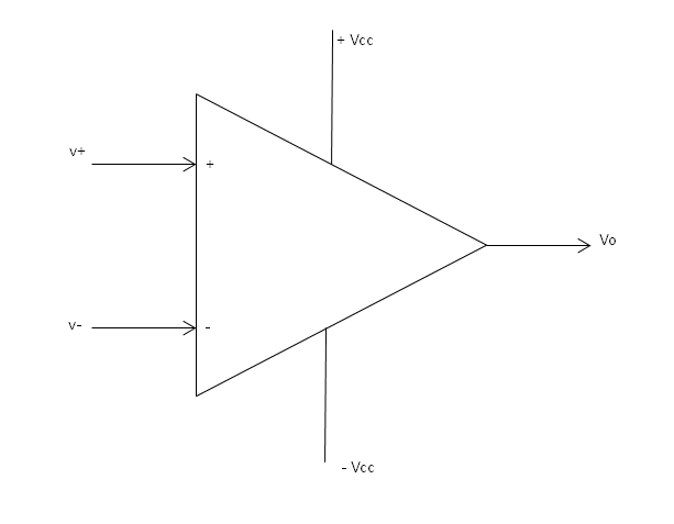
Where
- v+ is the non-inverting input
- v- is the inverting the input
- +Vcc represents the positive power supply terminal
- -Vcc represents the negative power supply terminal
- Vo is the op-amp output terminal
Most operational amplifier applications require dual polarity power supply on the +Vcc and –Vcc terminals. However, there are those that can operate from a single polarity power source. Usually, the power supply voltages of the op-amp influences the magnitude of the output voltage.
Block diagram of an operational amplifier
The operational amplifier has a differential input stage followed by the level shifter and finally the gain stage.
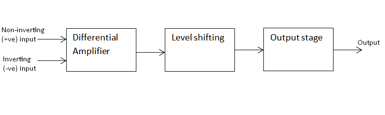
Differential amplifier
This is the stage compares the inverting and non-inverting inputs and then amplifies the resultant signal depending on which of the two is larger. The stage has a very high resistance and voltage gain. It also provides a high common mode rejection ratio.
Level shifter
An op-amp does not use coupling capacitors because it hands a wide range of frequencies including the dc level signals. Direct coupling causes the dc level to go higher as the signal moves from one stage to the other. This increase ends up shifting the operating point of the other stages hence distorting the output signal or limiting the output voltage swing.
To avoid this, the section shifts the output quiescent voltage from one stage before applying it as an input to the next stage.
Other times when shifting is necessary is when there is a need to ensure that the output is zero whenever there is no input signal. The level shifting stage has very high input impedance in order to prevent loading the gains stage.
Output stage
The output stage amplifies the signal from the differential amplifier. It consists of a high gain amplifier and is the stage that supplies the current to an external load.
Generally, it has a very low resistance, ideally zero. In a typical operation, the stage must supply the output with a large voltage swing. The most common design from the output stage is the complementary emitter follower utilizing high gain transistors such as the Darlington pairs.
Ideal characteristics of op-amps
When designing or analyzing the operational amplifier circuits, it is important to make some assumptions. This allows the designers to treat the op-amp as an ideal device with the following characteristics.
- Infinite input impedance
- Infinite open-loop gain
- A zero output impedance
- Balanced such that there is no output whenever the two input signals are equal.
- Infinite bandwidth
- Properties do not change with temperature
- Infinite Common-mode rejection ratio (CMRR)
In actual devices, the above characteristics differ from the ideal values as explained below
Gain
The amplifier does not have an infinite gain but has a very large one that falls between 10000 and 100,000.
Generally, in the open loop configuration, the difference in the input signal is amplified several thousand times to produce a very large output voltage. Although the output is ideally very high, it cannot exceed the supply voltage.
Zero offset voltage
The output voltage from the amplifier should be zero when the inverting and non-inverting inputs are the same or grounded, hence a difference of zero. However, this does not happen in practical devices and they usually exhibit some offset voltage due to device imbalances and other issues.
Bandwidth
An ideal op amp has infinite bandwidth, hence the ability to amplify all signals starting from DC to the highest frequency. However, in practical op-amp devices, the bandwidth is finite and dependent on the Gain-Bandwidth (GB) which refers to the frequency at which the gain of the amplifier becomes unity.
Typical operational amplifier configurations and applications
The operational amplifier is used in a wide range of analog and digital applications in the scientific, industrial and consumer products.
Using the feedback, with or without external components, it is possible to design an op-amp circuit that performs the desired function. The types, values, and configuration of the feedback components between the input and output terminals determine the operation and output of the amplifier.
For example, the resistor-based feedback networks provide functions such as amplification, subtraction, addition, and others. Combining the resistors and capacitors enables the operational amplifier circuits to perform differentiation and integration functions as well as signal conditioning such as filtering.
Basically, there are two common types of operational amplifier configurations; the open loop and closed loop circuits.
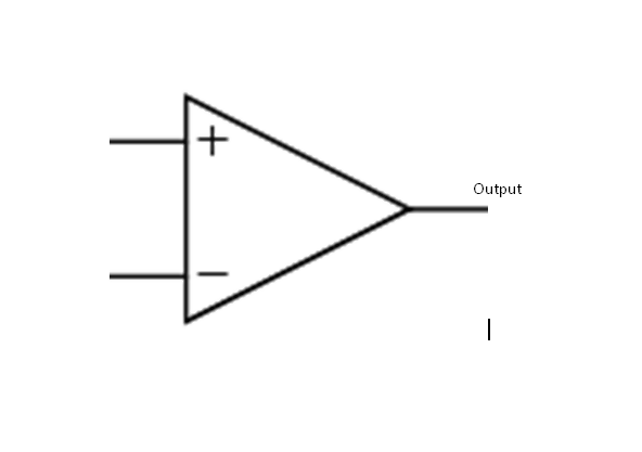
Open loop configuration
This does not have any feedback and the op-amp circuit in such a configuration is referred to as a comparator. The circuit can determine which of the two inputs is larger. If equal, there is no output. However, if the inverting signal is bigger, the output equals the positive supply voltage. A larger non-inverting signal causes the op-amp to produce an output equal to the negative power supply voltage.
Closed loop configurations
The closed loop operation involves adding the feedback signal to one of the input terminals.
Positive feedback
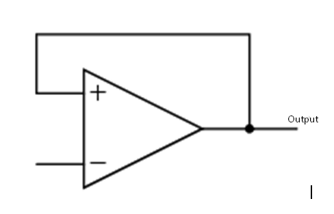
In this configuration, all or a fraction of the op-amp output is fed back to the non-inverting input. The feedback voltage is in phase with the input, hence a larger overall gain for the amplifier.
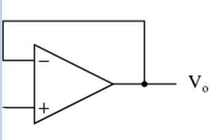
When the output signal is connected directly to the input terminal, the circuit provides a constant unity gain. However, adding a feedback resistor between the output and the input terminal provides a lower gain based on the value.
Typical applications for this configuration include the Schmitt Trigger Oscillator
Negative feedback configuration
The feedback signal is connected to the inverting terminal. Applications that utilize the negative feedback include;
- Differentiator, Integrator, Active RC filters
- Instrumentation amplifiers
- Summation, subtraction, inverting and non-inverting amplifiers
- Current to voltage and voltage to current converters
Typical applications of the operational amplifiers
- Summing amplifier such as audio mixers, Audio pre-amplifiers, DC level control, etc.
- Analog calculators
- The voltage or current regulators
- Analog-to-digital converters, digital-to-analog converters
- Instrumentation amplifiers, precision peak detectors, etc.
- Active filters such as bandpass, low pass, or high pass filters, etc.