In the realm of electronics, the printed circuit board (PCB) forms the heart and backbone of virtually every device. From the simplest household gadget to the most complex aerospace systems, PCBs provide not just mechanical structure but also electrical connectivity and signal routing. Over the years, PCB designs have evolved to meet diverse requirements—miniaturization, flexibility, high density, and enhanced thermal performance.
Today’s engineers can choose among many board types, such as rigid, flexible, rigid-flex, high-density interconnect (HDI), metal-core, and ceramic PCBs. Each caters to unique applications, from wearable electronics to automotive safety systems, demanding a careful understanding of strengths, limitations, and manufacturing complexities. This article delves deeply into the various PCB types, their characteristics, use cases, design considerations, and production challenges—as well as emerging trends transforming the industry.
1. Rigid PCBs
Overview and Construction
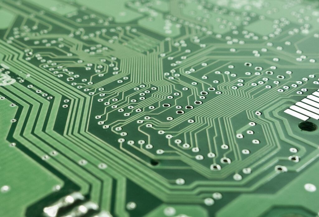
Rigid PCBs, constructed on solid, inflexible substrates like FR-4 (glass-fiber epoxy), are the most common and cost-effective board type. Their multilayer variants—ranging from two to over ten layers—allow complex circuit routing while maintaining structural integrity. Layers are laminated under heat and pressure, with copper etched to form conductive traces. Vias—plated through holes, blind, or buried—connect different layers electrically.
Use Cases and Advantages
Widely used in consumer electronics, computer hardware, industrial controllers, and home appliances, rigid PCBs excel in applications requiring stable, flat, and robust platforms. Their mechanical stiffness ensures reliable solder joints and component mounting. Additionally, their production scalability and low cost make them the default choice for mass-volume electronics. The rigid structure eases automated handling during assembly and supports high-speed signals with proper layer stack design and impedance control.
2. Flexible PCBs (Flex PCBs)
Overview and Construction
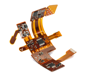
Flex PCBs are built on flexible substrates such as polyimide or polyester films, allowing boards to bend, fold, or twist. They typically come in single- or double-sided versions, though multilayer flex boards exist for more intricate applications. The manufacturing process includes copper layering, adhesive or adhesive-less stacking, and coverlay (a protective flexible film). Flex boards may include controlled impedance traces and stiffeners (rigid inserts) for component mounting.
Applications and Benefits
Flex PCBs find their niche in compact, dynamic, or shape-constrained spaces. Applications range from foldable smartphones and laptops to medical wearables, aerospace harnesses, and automotive lighting. Their flexibility reduces interconnect weight and simplifies cable harnesses, replacing bulky connectors and wires. They also absorb mechanical vibrations, enhancing reliability in dynamic environments. Flex boards support signal routing through tight curves, enabling innovative form factors and lighter designs.
3. Rigid-Flex PCBs
Hybrid Construction and Advantages
Rigid-Flex PCBs integrate rigid and flexible sections into a single board, combining both worlds. Sections of rigid FR-4 layers are interconnected by flex layers, forming a multilayer stack. They are manufactured as a unified assembly, typically bonded via alternating rigid and flex dielectric layers. This approach minimizes connectors, reduces assembly complexity, and improves signal integrity.
Ideal Uses
Common in aerospace, medical devices, military, and high-end electronics, rigid-flex boards are favored for their reliability in demanding conditions. They support high-density interconnects, complex 3D assembly, and dynamic folding without soldered wires. Applications include portable diagnostic equipment, satellites, cameras, and drones. Although more expensive to manufacture and design, they dramatically reduce final assembly steps and failure points.
4. High-Density Interconnect (HDI) PCBs
Definition and Key Traits
HDI PCBs incorporate microvias, buried and blind vias, and finer lines/pitches, enabling high-density routing. These boards often employ sequential lamination, microdrilling, and laser-drilled microvias. The result is compact designs capable of supporting advanced processor boards and multi-core electronics, while preserving signal integrity at high speeds.
Use Cases and Execution
Foundational in smartphones, tablets, wearables, network equipment, and high-speed computing modules, HDI PCBs enable densely packed components with minimal footprint. They support advanced package-on-package (PoP) and complex RF modules. Manufacturing HDI boards demands tight tolerance control, precise registration, and sophisticated drilling/screening—contributing to elevated cost and lead times.
5. Metal-Core PCBs (MCPCBs)
Structure and Purpose
Metal-core PCBs integrate a metal layer—typically aluminum or copper—beneath the dielectric layer. The metal core acts as an excellent thermal conductor, drawing heat away from components like LEDs, power modules, and high-current regulators. The top layers still use standard copper traces on FR-4 or polyimide with proper dielectrics for insulation.
Applications and Thermal Management Benefits
MCPCBs shine in thermal-critical applications such as LED lighting, power conversion, automotive LED headlights, and power amplifiers. The metal substrate enables efficient heat dissipation, extending component life and preventing overheating. These boards reduce the need for bulky external heat sinks and make the design more compact. Trade-offs include higher weight and cost, as well as potential differences in thermal expansion requiring attention during component assembly.
6. Ceramic PCBs
Composition and Thermal Advantages
Ceramic PCBs use substrates like alumina (Al₂O₃), aluminum nitride (AlN), or beryllium oxide. Known for excellent thermal conductivity, low dielectric loss, and high-temperature stability, ceramic boards serve niche yet critical roles. Some designs support thin-film technology for even higher interconnection density and performance.
Specialized Applications
Ceramic PCBs are common in power electronics, aerospace avionics, RF/microwave components, and high-power LED systems. Their ability to withstand harsh environments, high heat, and radiation (e.g., space) makes them indispensable in demanding domains. Ceramic boards are costly and brittle, often requiring precise handling and bonding. Their manufacturing involves specialized processes like silk-screened metallization and brazing.
7. Rugged and Flexible Hybrid Boards
Definition and Key Features
This category spans ruggedized boards meant for harsh environments—using thicker board materials, conformal coatings, and military-grade components—and advanced hybrids like very thin flexible laminates with embedded components or copper foil sandwiched between polymer layers. Stackups may utilize exotic materials like PTFE for RF applications.
Application Spectrum
Used in military rugged hardware, industrial control gear, oil and gas monitoring systems, and high-frequency communication modules, these boards require durability, electrical performance, and environmental robustness. For instance, rugged PCBs might include reinforced vias, excessive copper weight, and protective coatings to resist moisture, chemicals, and shock.
Detailed Comparison and Design Tradeoffs
Both rigid and flex PCBs have their strengths, and hybrid forms like rigid-flex and HDI blur traditional lines. Choosing the right type depends on criteria like mechanical flexibility, thermal constraints, assembly process, and cost.
-
Cost & Manufacturing Complexity: Rigid boards are cheapest and easiest to produce. HDI and rigid-flex boards command higher costs and tighter tolerances.
-
Thermal Performance: Metal-core and ceramic boards outperform standard FR-4 in heat dissipation.
-
Density & Miniaturization: HDI and ceramic boards enable the smallest footprints and highest signal density.
-
Environmental Tolerance: Ceramic and rugged boards survive extreme heat, vibration, and radiation; standard rigid may suffice for benign environments.
Emerging Trends and Future Directions
-
Embedded Components – Integrating passive (and eventually active) components within inner layers, reducing real estate and boosting signal performance.
-
Additive Manufacturing (3D Printed PCBs) – Prototyping or low-volume boards using conductive inks for rapid design iterations.
-
Flexible Stretchable Circuits – For wearable and biomedical electronics, these going beyond flex-foil into elastomer substrates.
-
Thin HDI for IoT – Ultra-thin, multi-layer HDI boards serving smart sensors and connected devices demanding minimal volume and maximal connectivity.
Conclusion
Printed circuit boards are far more than static interconnect fabric—they are dynamic enablers of modern electronics innovation. Whether simple or cutting-edge, choosing the right PCB type affects not only product function and manufacturability but also long-term reliability, regulatory compliance, and user experience.
-
Rigid PCBs remain the workhorse.
-
Flex and Rigid-Flex boards unlock complex form factors and reduce connectors.
-
HDI delivers dense, high-speed circuitry in small footprints.
-
Metal-core and Ceramic designs handle thermal and environmental extremes.
-
Rugged hybrids ensure durability where failure isn’t an option.
As electronic products become smarter, smaller, and more demanding, PCB technology must continue to evolve. By understanding and selecting the appropriate board type—paired with thoughtful design and fabrication techniques—engineers can deliver devices that meet both current requirements and tomorrow’s challenges.