In modern electronics, compliance is not just a regulatory checkbox — it is a core pillar of product success. Whether your device is destined for consumer markets, industrial plants, medical facilities, or aerospace applications, it must meet a web of standards covering safety, electromagnetic compatibility (EMC), environmental responsibility, and performance reliability. Failure to comply can lead to costly redesigns, failed certification tests, recalls, or outright market rejection.
One of the most critical yet sometimes underestimated aspects of achieving compliance is component-level design consideration. The choice of resistors, capacitors, semiconductors, connectors, and PCB layout strategies directly determines whether the final product will pass compliance testing. This means engineers must think about voltage ratings, thermal limits, EMI/ESD mitigation, and regulatory certifications before the first prototype is built. By embedding compliance thinking early in the component selection and design stage, companies can dramatically reduce project risk, save costs, and ensure faster market entry.
Below, we’ll explore the key component design considerations for compliance, drawing from the In Compliance Magazine reference article, complemented by best practices from other industry sources.
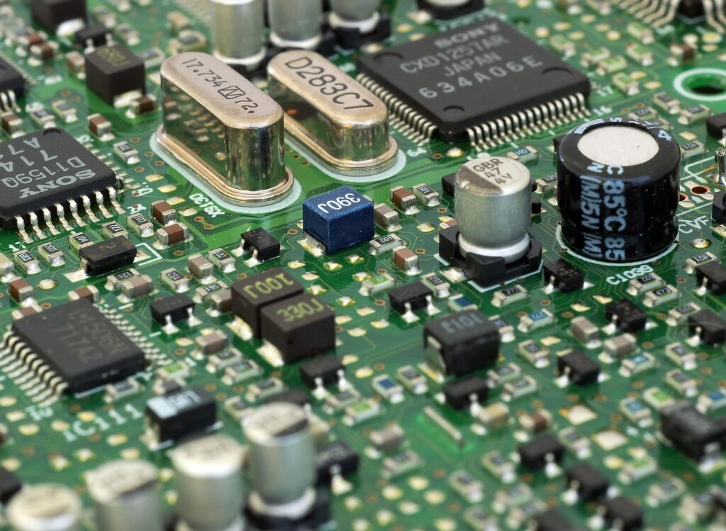
1. Component Selection
Voltage Ratings & Safety Margin
Selecting components with adequate voltage ratings is essential for avoiding insulation breakdown and ensuring safety. Regulatory bodies often require that components operate well below their maximum rated voltage — typically with a safety margin of 20–50%. This prevents failure during voltage surges or abnormal operating conditions. For example, a capacitor rated at 50 V should not be routinely used in a 48 V circuit; real-world voltage spikes could cause it to fail prematurely. Using appropriately rated components also improves the chances of passing dielectric withstand voltage (hipot) and insulation resistance tests during certification.
Beyond ratings, engineers should consider derating guidelines from IPC-9592B or MIL-HDBK-217, which account for environmental stresses such as temperature, vibration, and humidity. Derating not only boosts reliability but also aligns with safety standards like UL and IEC, which expect a margin between component specifications and actual usage conditions.
Tolerance & Signal Integrity
Component tolerance — the allowable variation from a nominal value — plays a crucial role in maintaining circuit performance and compliance. High-tolerance drift can lead to excessive harmonics, poor filter performance, or out-of-spec clock signals, potentially failing EMC or functional safety tests. For example, a timing capacitor in a crystal oscillator with ±20% tolerance could shift the clock frequency enough to cause EMI emissions to exceed CISPR/FCC limits.
Using low-tolerance components ensures predictable performance under varying conditions. For signal integrity in high-speed designs, matched impedance components and tight tolerance resistors (e.g., ±0.1%) are often necessary to reduce reflection and crosstalk, both of which could create radiated EMI that compliance labs would detect.
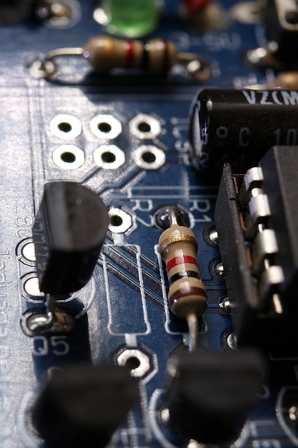
2. PCB Layout & Placement
Minimize Current Loop Areas
One of the most effective ways to reduce EMI emissions is by minimizing the size of current loops in the PCB layout. Large loop areas act as antennas, radiating electromagnetic noise into the environment. To control emissions, return paths should be routed close to their corresponding signal traces, and differential pairs should be kept tightly coupled.
This is particularly important in switching power supplies, high-speed data lines, and clock circuits. For example, in a buck converter layout, placing the input capacitor as close as possible to the MOSFET and diode loop reduces both radiated and conducted emissions. These strategies align with best practices in IEC 61000 EMC standards.
Ground Management
Ground strategy is a cornerstone of EMC compliance. Poor grounding can create ground loops, increase susceptibility to interference, and worsen radiated noise. Separating analog and digital grounds and connecting them at a single “star” point helps isolate noise-sensitive analog circuits from noisy digital domains.
Solid ground planes also reduce impedance in return paths, improving signal quality and lowering EMI emissions. For high-speed designs, a continuous ground plane beneath signal traces provides both shielding and a low-inductance return path. Compliance testing for immunity (e.g., IEC 61000-4-6 conducted immunity) often exposes weaknesses in grounding strategy.
3. Thermal Management
Heat Sinks & Thermal Vias
Excess heat not only reduces component lifespan but can cause immediate functional failures, leading to failed compliance tests related to safety and endurance. Many standards, including UL 60950 and IEC 62368, require products to maintain safe surface and internal temperatures under fault conditions. Heat sinks, thermal pads, and strategically placed thermal vias can help manage hot spots and dissipate heat efficiently.
Thermal vias connect heat-generating component pads to internal copper planes or the opposite PCB side, increasing thermal conduction. This design choice can be the difference between passing and failing thermal stress tests, particularly for power electronics.
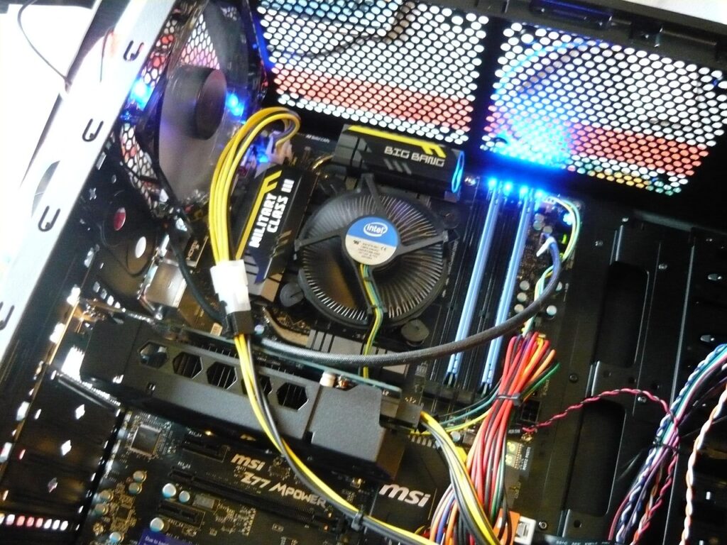
Active and Passive Cooling
Passive cooling techniques like increased airflow paths, component spacing, and heat spreaders often suffice in low-power designs. However, high-power or densely packed electronics may require active cooling such as fans or even liquid cooling systems. The design must consider dust ingress, vibration, and noise, all of which may affect compliance with environmental and safety standards like IP ratings or IEC 60068.
Choosing cooling methods also affects electromagnetic compliance. For example, fans can introduce noise into the system unless filtered or shielded. This interaction between thermal and EMI considerations is a critical area for cross-disciplinary design thinking.
4. EMI/EMC, ESD, & Transient Immunity
Protection Against Electrical Events
Transient events such as electrostatic discharge (ESD), electrical fast transients (EFT), and surges can cause catastrophic failure or subtle performance degradation. Standards like IEC 61000-4-2 (ESD immunity) and IEC 61000-4-4 (EFT immunity) define test levels that products must withstand. Designing with transient voltage suppression (TVS) diodes, metal oxide varistors (MOVs), ferrite beads, and common-mode chokes can significantly improve immunity.
Selecting the correct suppression components involves balancing clamping voltage, response time, capacitance, and power handling. For example, a TVS diode with too high a clamping voltage may not protect sensitive ICs, while one with too much capacitance could degrade high-speed signals.
Cabling Considerations
Cables are both antennas and antennas’ favorite friends — they can radiate EMI or bring interference into the device. Shielded cables, twisted pairs, and filtered connectors can help control conducted and radiated emissions. Cable routing within the product enclosure should avoid running noisy power lines alongside sensitive signal lines.
Compliance testing often involves swapping cables or injecting noise into them to check product immunity. Early design for cable management can save hours of troubleshooting and costly redesign at the EMC lab.
5. Proactive Compliance in Product Design
Early Integration of Compliance
Waiting until late in the design cycle to think about compliance is a recipe for failure. Early integration means that from the first schematic, every design choice — from component footprints to enclosure material — is made with regulatory standards in mind. This approach reduces redesign cycles, lowers costs, and shortens time to market.
Involving compliance engineers early also ensures that the design aligns with region-specific regulations (FCC in the US, CE in Europe, VCCI in Japan, etc.), as different markets have different test limits and certification procedures.
Software & Supply Chain Tools
Compliance isn’t only about hardware — tracking the environmental compliance of materials (RoHS, REACH) and ensuring supplier components maintain certifications is equally important. Supply chain compliance tools can automatically track component statuses, issue alerts for obsolescence, and flag non-compliant materials.
Maintaining an up-to-date compliance database also helps during audits and when producing technical files for CE marking. This proactive tracking helps avoid scenarios where a compliant product suddenly becomes non-compliant due to a supplier’s unnoticed component change.
Compliance Checklist for Engineers
-
Voltage & Derating – Always apply a 20–50% safety margin.
-
Tolerance & Drift – Use low-tolerance parts for timing and filtering.
-
Grounding Strategy – Maintain continuous ground planes and avoid loops.
-
Thermal Control – Use heat sinks, vias, and airflow planning.
-
Transient Protection – Include TVS, MOVs, and filters for surge and ESD events.
-
Cable Management – Use shielded, twisted, and well-routed cables.
-
Documentation – Keep compliance test plans, material declarations, and certification proofs updated.
-
Cross-team Review – Involve compliance engineers from concept to production.
Summary
To design compliant electronics, you need to thoughtfully integrate component choice, layout strategy, thermal control, and robust EMI/ESD protection. Most critically, start compliance planning early—this streamlines certification, lowers costs, and ensures product safety and reliability.